
Management Of Curved Canals: Part I - From Case Assessment To Glide Path Preparation.
06/12/2025
Fellow
Warning: Undefined variable $post in /home/styleendo/htdocs/styleitaliano-endodontics.org/wp-content/plugins/oxygen/component-framework/components/classes/code-block.class.php(133) : eval()'d code on line 2
Warning: Attempt to read property "ID" on null in /home/styleendo/htdocs/styleitaliano-endodontics.org/wp-content/plugins/oxygen/component-framework/components/classes/code-block.class.php(133) : eval()'d code on line 2
The mechanical preparation of the root canal system is generally acknowledged as one of the most crucial stages in root canal treatment (1). Many in vitro studies, including those of Weine et al. and Glickman & Dumsha, have described that the instrumentation of root canals can result in iatrogenic errors such as instrument fractures, transportation, asymmetrical dentine removal, ledging, and perforations (2,3). Altered root canal morphology may not be a direct cause of treatment failure; however, it has been linked to poor treatment outcomes because parts of the root canal system remain inaccessible for disinfection (4). Procedural mishaps are reported to occur more frequently in curved canals due to the torsional and bending forces that are developed during their instrumentation, resulting in uneven forces against the root canal walls (5,6). Although the introduction of new NiTi alloys and shaping techniques has minimized preparation errors, the management of severely curved root canals still remains a significant clinical challenge.

Fig. 1
Fig. 1 Case Assessment
The management of curved canals begins with the appropriate assessment of the case in the periapical radiograph. Multiple images with different horizontal angulation might provide additional information. However, periapical radiographs provide data only for the proximal curvatures, while the majority of root canals are curved in multiple planes and degrees (7). The use of CBCT may be needed in some cases to overcome the limitations of the two-dimensional image and create a personalized treatment plan (8).
Two preoperative x-rays with different horizontal angulation in a case of a previously treated #16 in a 46-year-old female patient with symptomatic apical periodontitis depicted better the tooth’s anatomy. In particular, the x-rays not only revealed that the mesial root is curved 3-4mm from the radiographic apex, but also that a straightening and perforation of the mesial root canal may have taken place (straight radiolucent line prior to the curvature).
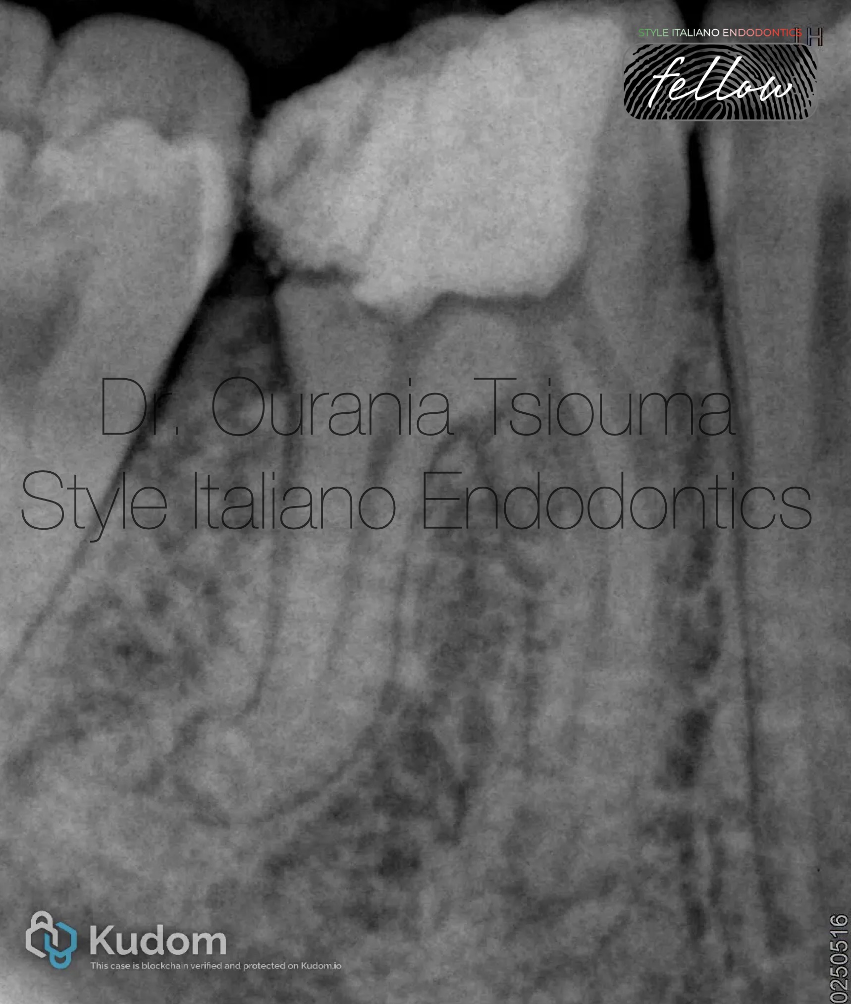
Fig. 2
Defining the geometrical and anatomical characteristics of the curvature will help the clinician plan a predictable instrumentation protocol for managing challenging anatomies. Although there is no consensus for their measurement, the following can be concluded from the literature (6,9);
The following geometrical characteristics of the distal root on tooth #46 with previously initiated therapy in a 37-year-old female patient are reported on the preoperative x-ray: Angle > 25o, small radius and length of the arc, location 1-2mm from the radiographic apex.
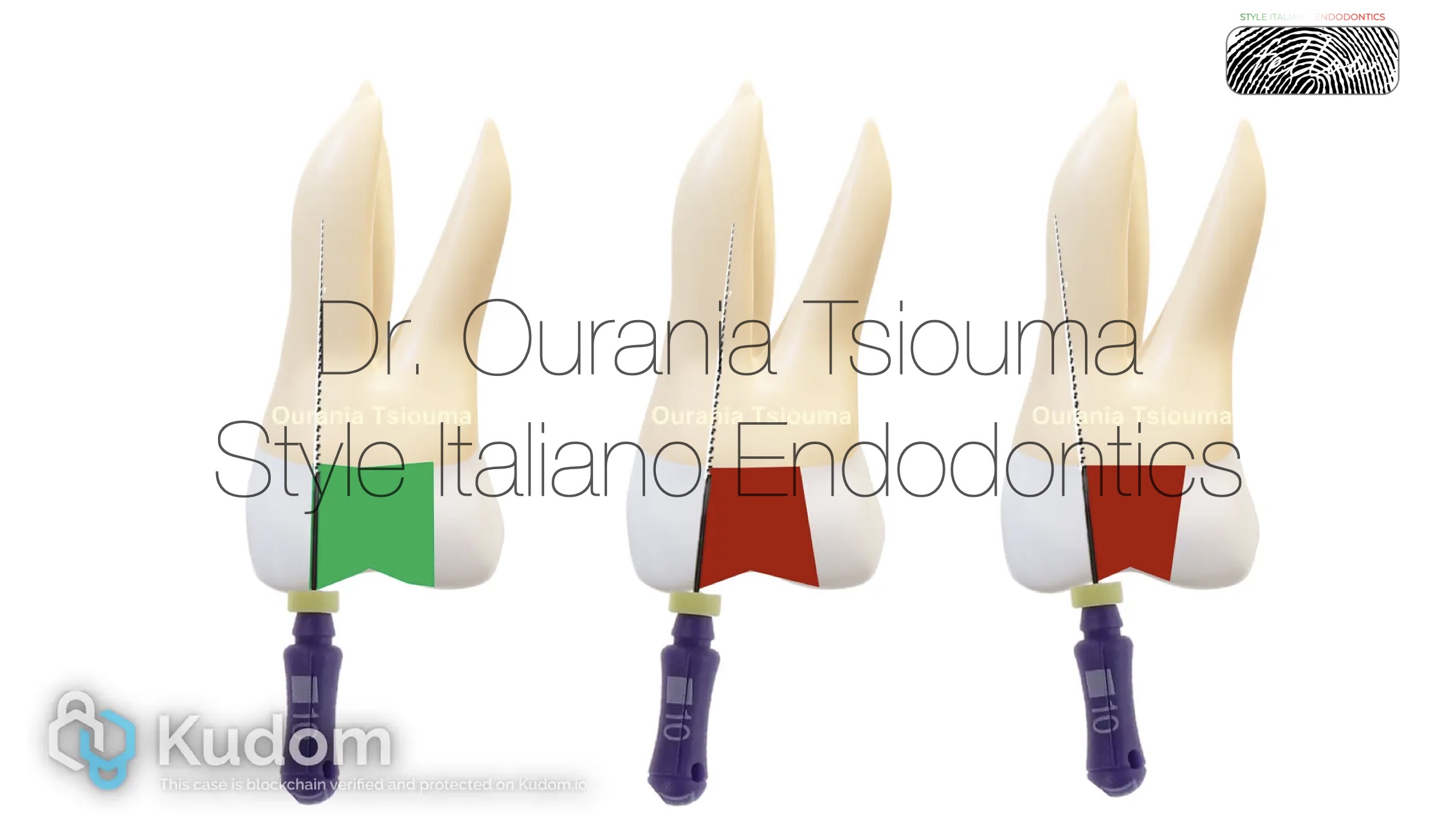
Fig. 3
Clinicians should try to minimize the tooth structure loss during access cavity preparation. However, minimally invasive access cavities usually create for the instruments a curved path to the apex, thus they may increase the chance of iatrogenic errors compared to traditional preparations. Moreover, minimally invasive designs do not seem to increase the fracture resistance of root treated teeth (10). Given the available evidence, we suggest that the access cavity should be as small as practical and provide a straight, smooth, unobstructed pathway to the root canal system and ultimately to the apical area or position of the first curve.
.
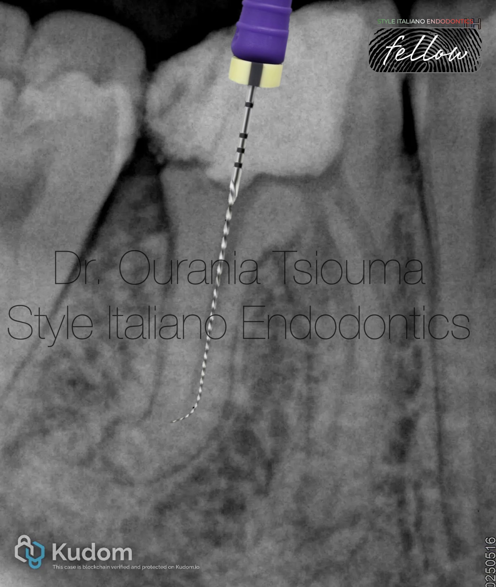
Fig. 4
In curved canals it is impossible to reach the working length (WL) at once. Negotiation of such cases is usually performed using small and precurvedstainless steel K-files (sizes 06 to 10) in a watch-winding motion. Straight files should not be forced inside the canal because its original anatomy may be altered. Some instructions for precurvingare as follows (6,11,12):
.

Fig. 5
The difficult part in such cases is for the file to maintain the prebending when it is inserted into the root canal. In constricted canals, the bent tip will be curled or straightened when an attempt to advance the file is made. Preflaring (preliminary enlargement) of the coronal third to 2/3 of the root canal will allow the file to maintain its prebending until the apical third. Other advantages of preflaring: reduced torsional stress of the file, fewer contact points of the file with the dentin walls, better tactile sensation, enhanced irrigant penetration, more reliable WL measurement, and creation of an unimpeded pathway to the curvature. Tools for preflaring include Gates Gliddens drills, large hand files, dedicated NiTi orifice openers (used as a single instrument), and NiTi instruments (used mainly in a crown-down sequence). The latter two are used nowadays with greater safety and predictability. Preflaringmight be repeated several times before reaching the WL and should be done at least 1mm shorter than the scouting length so a ledge won’t be created. The size of the pre-enlargement is not standard and is dependent on the geometrical characteristics of the curvature (6,11).
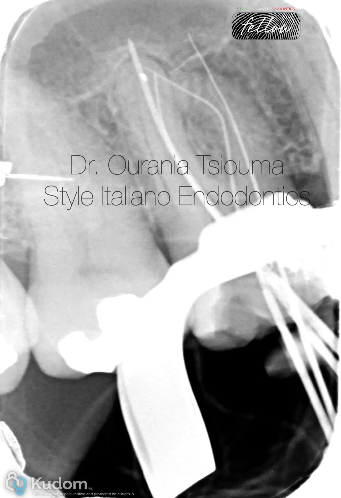
Fig. 6
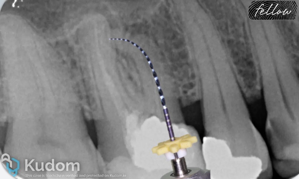
After scouting and coronal preflaring, the file is advanced through the canal using a watch-winding motion. If the file cannot negotiate beyond the curvature, it should be withdrawn 1mm, turned in a new direction with a subtle clockwise motion, and then moved again apically. This step should be repeated until some advancement is made. If the file curvature and the canal curvature (angle of access and angle of incidence) do not match, or the file tip is straightened, apical progress will not be made. The file should not be pushed, but rather withdrawn, recurved, and used again. Many attempts with patience and careful probing might be necessary in challenging cases. As soon as the file tip moves beyond the curvature, it will advance deeper into the canal. At this point, do not withdraw the file to the impediment level, but apply the envelope of motion. The envelope will remove restrictive dentin from the curvature, making it smoother and easier to negotiate. After the curvature is negotiated, the apex locator is used to check whether the terminus has been reached. Upon reaching the WL, the file should not be removed, but used with small 0,5-1mm amplitude coronal-apical vertical strokes, because it may be difficult to reach this point again (6, 12-14).
In the x-ray, the MB1 original canal anatomy could not be negotiated past the perforation, but the curvature was successfully managed in the MB2 canal.
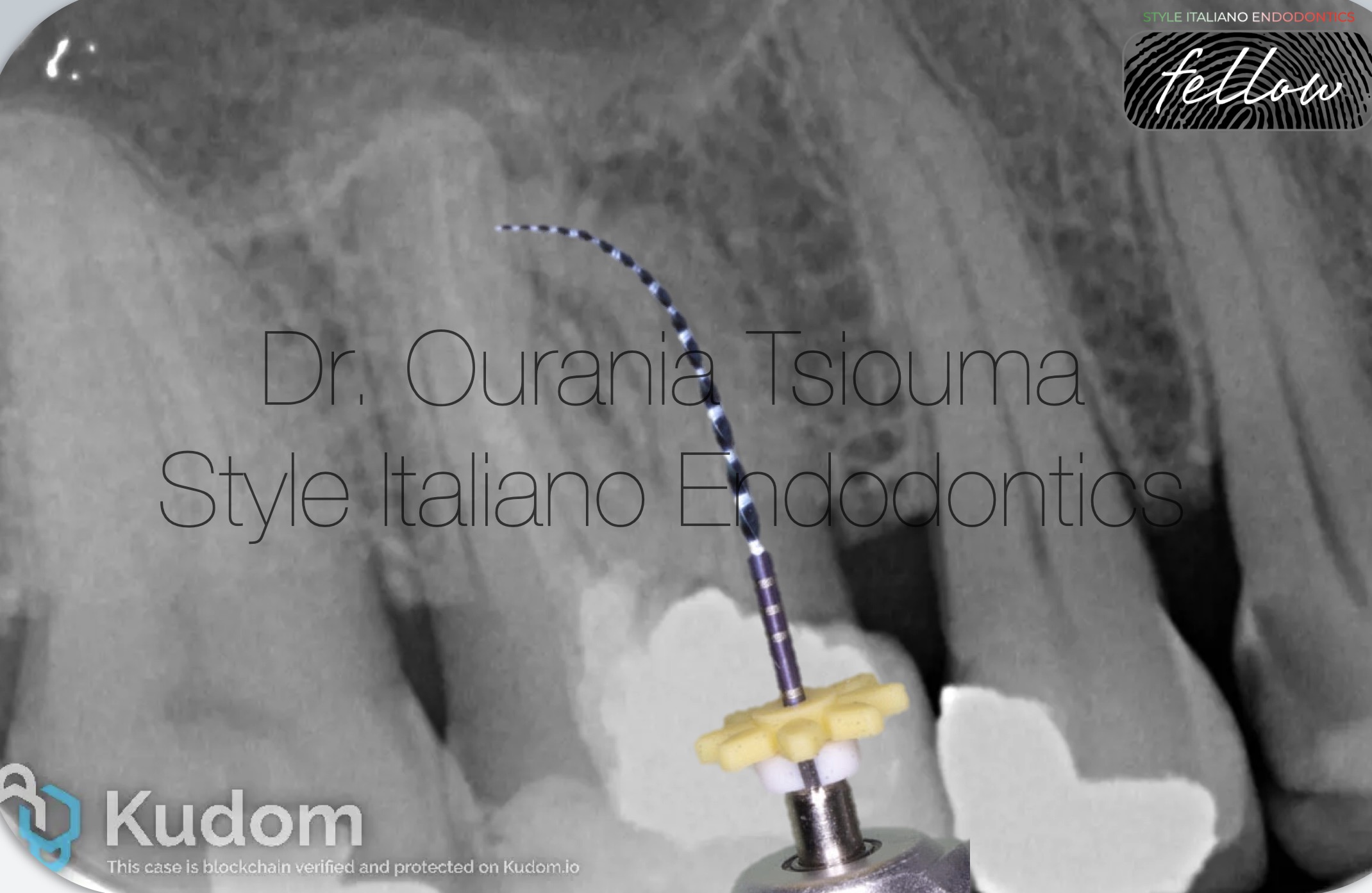
Fig. 7
The term glide path is defined as a smooth canal tunnel, usually with a small taper, from the canal orifice to the physiologic terminus. The glide path will secure an open pathway that subsequent rotary instruments can follow, preventing instrument blockage or taper lock. The typical minimum glide path size should be a super loose size #10 to #20 K-file. After the size #10, the glide path can be created either manually or with rotary instruments. If manual files equal or larger than size #15 are to be used, then the balanced force motion should be applied. Intermediate file sizes #12,17 may be useful. A variety of small rotary instruments have also been created to simplify the process. Each option has its own advantages and disadvantages, and it's up to the clinician to choose which method to utilize. However, it should be noted that the engine-driven glide path preparation produces significantly fewer canal aberrations compared with manual glide path preparation and is more predictable in the hands of inexperienced operators. Rotary files for glide path creation should be used according to the general principles for rotary instrument usage or with the Tactile Control Activation (TCA) technique in challenging cases (6, 12-15).

Fig. 8
Fig.10
About The Author:
Ourania Tsiouma
-2016: Award of Excellence in the Physiology course from the Laboratory of Experimental Physiology, Medical School, National and Kapodistrian University of Athens.
-2015-2019: <<Antonios Papadakis>> scholarship holder during her undergraduate studies.
-2019: 1st "Ioannis Karkatzoulis" Prize for the best Oral Presentation in the 19th Pampeloponnesian Dental Congress.
-2020: Graduated second with honours from the Dental School of the National and Kapodistian University of Athens, Greece.
-2020–2022: Research Associate in the Department of Endodontics, Dental School, University of Athens, Greece.
-2023: Master in Clinical and Surgical Microendodontics, University of Turin, Italy.
-2024 - : Postgraduate student, Master of Science in Endodontics, Dental School, University of Athens, Greece.
-Author of scientific articles published in national and international peer-reviewed journals.
-Fellow Member of Style Italiano Endodontics.
-Private practice focused on Endodontics and Restorative Dentistry in Athens, Greece.
Conclusions
The management of curved canals remains a major issue in Endodontics. Severe root canal curvatures pose a challenge in all stages of root canal treatment. A thorough case assessment, along with appropriate instrumentation techniques and customized treatment planning, will enhance the quality of treatment. Patience and many careful attempts may be required.