A synopsis about the first phases of canal shaping
29/07/2016
Paolo Generali
Warning: Undefined variable $post in /home/styleendo/htdocs/styleitaliano-endodontics.org/wp-content/plugins/oxygen/component-framework/components/classes/code-block.class.php(133) : eval()'d code on line 2
Warning: Attempt to read property "ID" on null in /home/styleendo/htdocs/styleitaliano-endodontics.org/wp-content/plugins/oxygen/component-framework/components/classes/code-block.class.php(133) : eval()'d code on line 2
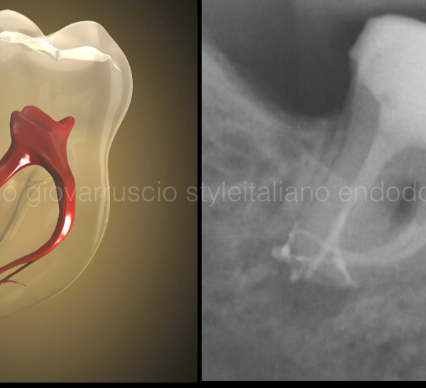
After the last articles, by Fabio Gorni, Massimo Giovarruscio and Enrico Cassai, it is important to make a point of preflaring, scouting and glide-path preparation, the first phases of canal instrumentation.
We have proposed a new classification of endodontic instruments based upon their clinical use, depending on the distinct phases of the endodontic treatment, namely:
- Elimination of the coronal interferences
- Scouting
- Glide path preparation
- Final shaping
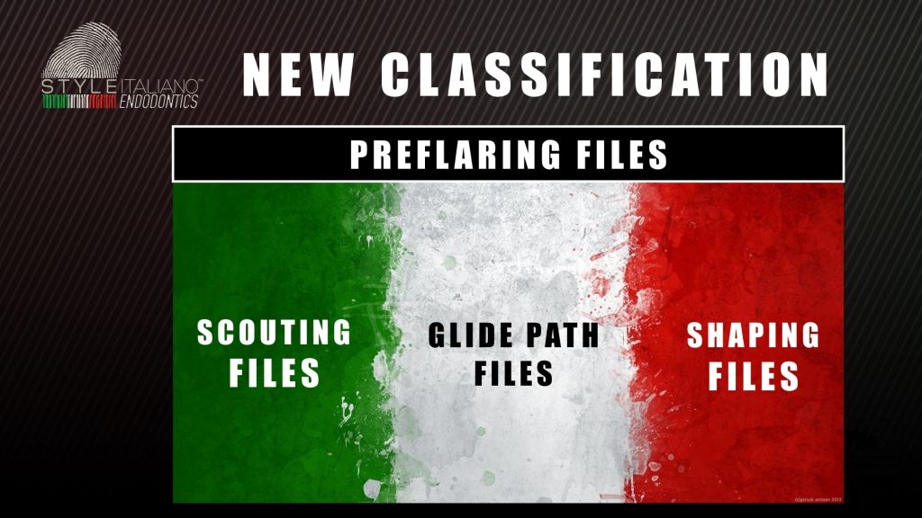
Fig. 1
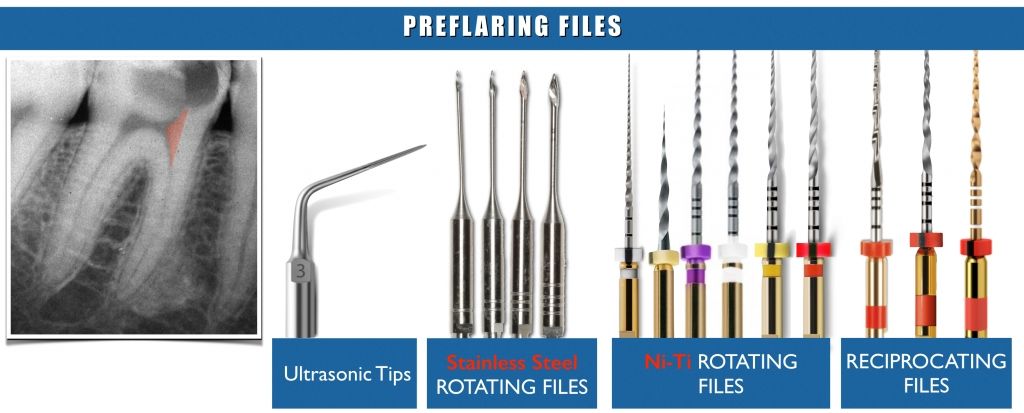
Fig. 2
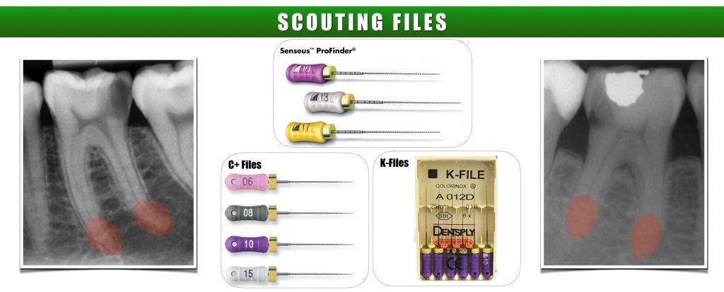
Fig. 3
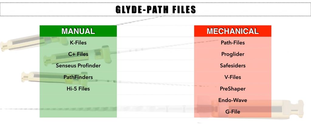
Fig. 4
First of all, according with a review by Jafarzadeh & Abbott (JOE 2007), during the first phases the clinician frequently finds procedural difficulties. These problems include instrument fracture, ledge formation, canal zipping or canal straightening, strip perforation, apical perforation, elbow formation and apical blockage. All of these errors can lead to incomplete debridement of the root canal system and contribute to decreased success rates of endodontic therapy. Access cavity, a topic that will be addressed later in another series of articles, should be large enough to allow entry into all canals, while preserving tooth structure for future restoration. The access cavity should be as small as practical.
Cervical or early preflaring plays a vital role in reducing the discrepancy between initial apical file diameter and apical canal diameter. It also has frequently been reported that manual or mechanical pre-flaring is very important to reduce the incidence of instrument separation.
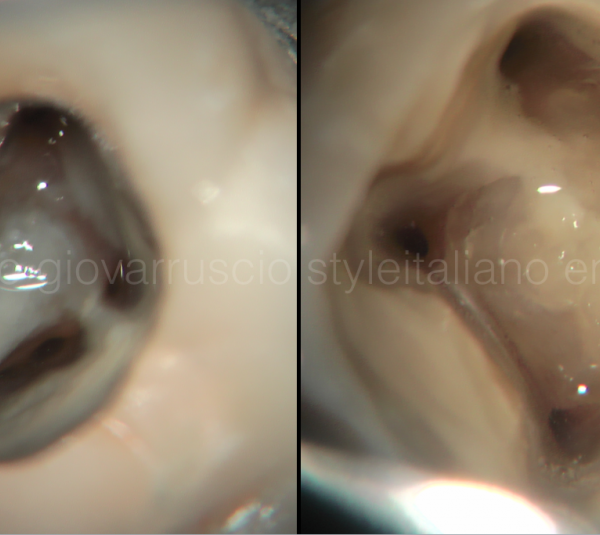
When straightline access has been completed and all the orifices have been identified, the smaller stainless steel files are measured on the pre-op x-ray, and prebend to conform to the anticipated full length and curvature of the root canal.
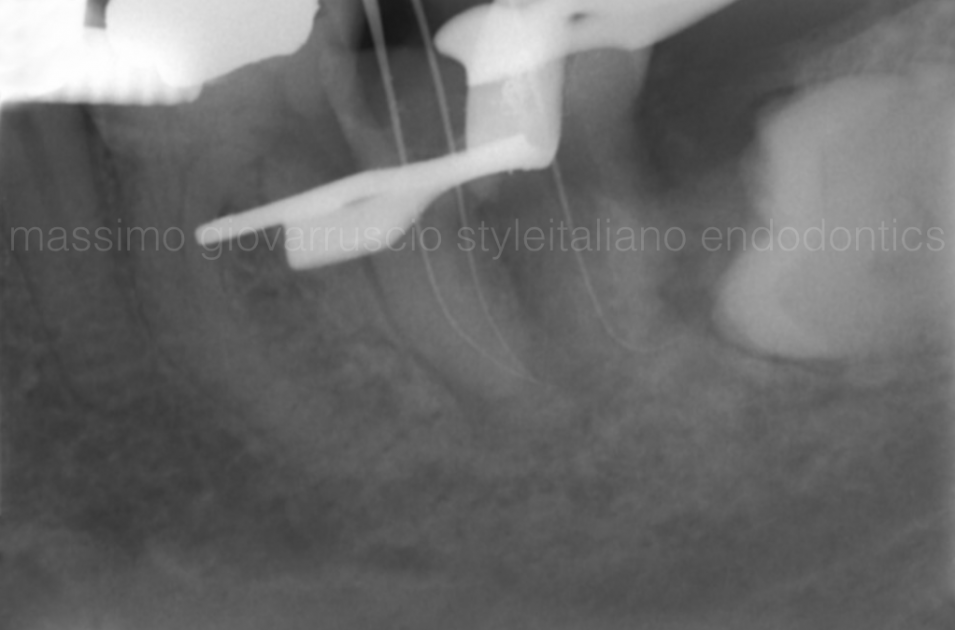
Fig. 5
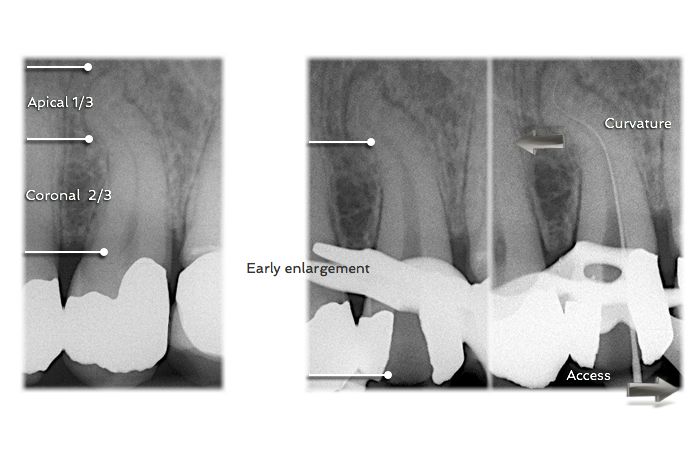
Stainless steel 10K hand files, 0,02 tapered, can be used to explore or scout the coronal 2/3 of the root canal. After negotiation the coronal 2/3, the canal is flushed with NaOCL and may be pre-enlarged using hand instruments, gates glidden drills with brushing motion, or rotary NiTi shaping files. With the coronal 2/3 optimally prepared and filled with irrigant, the apical 1/3 is then scouted and information gathered. Small hand files are used (08K or 10K file) to negotiate the rest of the canal, confirming a smooth glide path to the terminus and establishing patency. The apical foramen will always be larger than a 10K file; therefore any resistance met prior to the apex is likely due to curvature or irregularity in the canal. As a result, opening up the canal with a 10K file in small increments can be an efficient way to create a reproducible glide path, while minimizing the likelihood of creating a ledge or blockage in the canal.
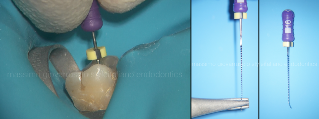
Fig. 6
The file should never be forced apically because the risk of creating a ledge is greatly increased. If the tip of the file never binds into the canal wall, it is impossible to make a ledge. When an impediment to apical progress is met, the file should be removed, smoothly bent at the very last 2mms, and used again with a a careful watch-winding motion. In challenging cases, many attempts may be required.
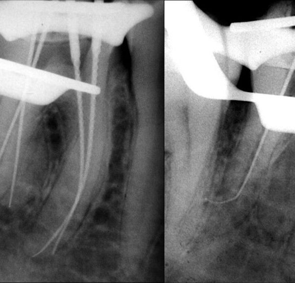
Now, the working length is determined with the electronic apex locator.
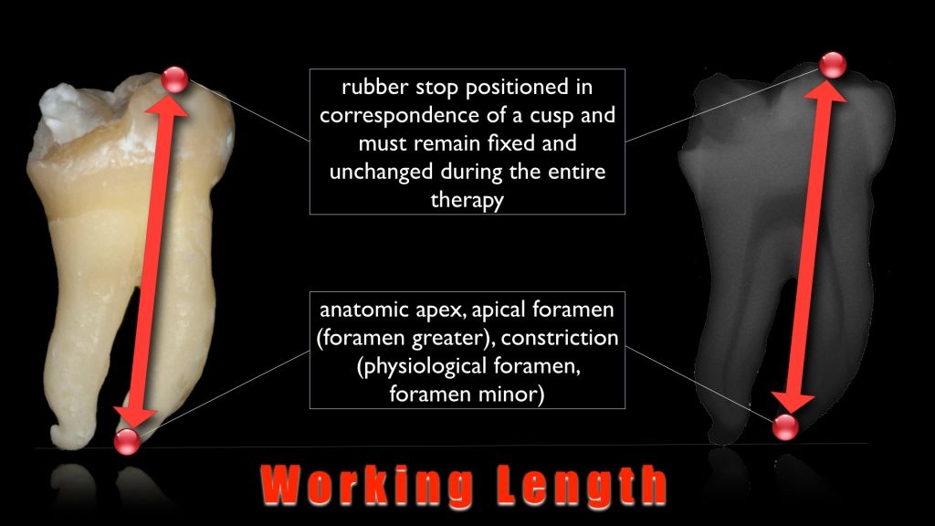
Fig. 7
Electronic measurement can be integrated with data obtained through tactile and radiographic method.
The next phase is the glide path. According with West (2010) a glide path is defined as a smooth radicular tunnel from the canal orifice of the canal to the physiological terminus of the root canal. A glide path does not need to be fabricated within the root canal, its a pre-existing part of the original tooth anatomy within the root. The glide path is nothing more than the natural space occupied by dental pulp. Due to anatomical variability, especially in the apical one third of the root, the glide path may be irregular in many teeth and great care must be taken to follow the natural path of the canal. In fact, to achieve a clean root canal system, the glide path needs to be followed, not made. Glide path is arguably the single most consequential clinical step that influences the successful fulfillment of the mechanical and biological goals for shaping canals.
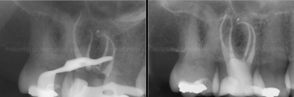
Fig. 8
If a 10K hand file can be easily passed to the estimated working length without any apical pressure, a more complicated technique to follow the glide path is unnecessary and will likely be a waste of time and materials. In complex anatomies with small, long and potentially multiplanar canals, it is not possible to immediately pass a 10K-file initially to the root end. Subsequently, the clinician may try to force smaller files to the apex. However, 06 and 08 files are typically not needed to enlarge the glide path to the apex unless it is an extraordinarily difficult case. The apical foramen will always be larger than a 10K-file; therefore any resistance met prior to the apex is likely due to curvature or irregularity in the canal. As a result, opening up the canal with a 10K-file in small increments can be an efficient way to follow a reproducible glide path, while minimizing the likelihood of creating a ledge or blockage in the canal.
After the 10 K-file, it is really important to consider that there is 50% increase between a 10 K-file and a 15 K-file, and 30% between the 15 K-file and the 20-K.
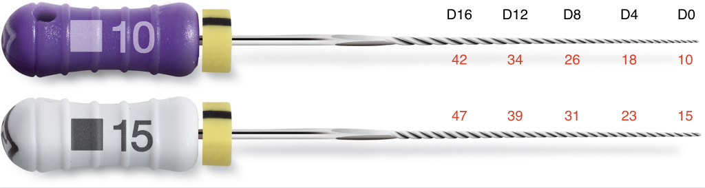
Fig. 9
The stiffness of these files may render their use challenging when attempting to treat constricted and curved canals. A better strategy is to work a size 10 hand file at length until it is super loose. A super loose size 10 file eliminates the need of utilizing a considerably stiffer, significantly larger, and substantially more dangerous size 15 SS file. This strategy is particularly important when securing more anatomically complex canals that are longer, narrower, and more curved. A 15K-File SS can be eliminated and replaced with a significantly more flexible, dedicated NiTi mechanical glide path file. When clinically using a glide path file, never push, peck, or force this file inward. Rather, let the glide path file passively and progressively advance along the secured portion of a canal. If the glide path file ceases to easily advance inward, remove the file and irrigate with NaOCl, recapitulate with a size 10 file to move debris into solution and reconfirm the glide path, then re-irrigate to liberate this loose debris.
Conclusions
This article summarizes the concepts exposed in the last articles, about the first phases of canal treatment. The next article, that will be published after the summer holidays, will show the final shaping techniques.
Bibliography
- Jafarzadeh H, Abbott PV. Ledge formation: review of a great challenge in endodontics. J Endod 2007;33:1155-62.
- Berutti E, Negro AR, Lendini M, Pasqualini D. Influence of Manual Preflaring and Torque on Failure Rate of ProTaper Rotary Instruments. J Endod 2004;30:228-230.
- Berutti E, Cantatore G, Castellucci A. Use of nickel-titanium rotary PathFile to create the glide path: comparison with manual preflaring in simulated root canals. J Endod 2009;35:408-412.
- West J. The endodontic glide path: Secret to rotary safety. Dent Today 2010; 29: 86-93